PTP Implementation and Point Timestamp Calculation

Overview
Cepton’s lidar sensors send out two kinds of packet on a regular basis: Point Data Packet and INFO Data Packet. Please refer Data Format for detailed structure information. Chapter 2 in this document outlines the implementation of Precision Time Protocol (PTP) in Cepton’s products to illustrate the generation of critical PTP related values reported in those two kinds of packets. These values are mainly used for displaying real-time system information, or run-time self-monitoring and diagnostic. Chapter 3 gives an example of how to use those reported values to calculate universal PTP timestamp for each point. Chapter 2 is for your better understanding, but you can skip this Chapter and directly refer to chapter 3 for usage only.
Reported Value Generation
Clock adjustment
Each slave clock maintains a local counter calculating the number of microseconds (us) since the sensor last booted up. When connection with PTP master clock becomes active, the clock adjustments shall perform synchronization and syntonization. Therefore, the universal PTP timestamp calculation is generally composed of three parts:
Synchronization eliminates the offset between slave’s counter and master’s clock. Syntonization matches the frequency of local clock to that of the Grandmaster Clock in the domain, which is measured by the slave's counter increases every drift interval, it is one nanosecond slower than the master's clock. Thus, the formula becomes more concrete:
Clock adjustments are carried out through a sequence of PTP timing messages exchange between upstream PTP Instance and local slave. The basic message exchange pattern is illustrated in IEEE Std 1588-2019 Figure 16 as shown below :
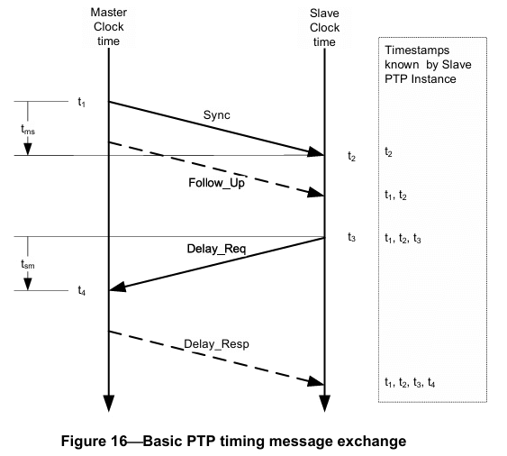
(a) The Master PTP Instance sends a Sync message to the Slave PTP Instance and notes the time t1 at which it was sent. The timestamp t1 can be embedded in the Sync message or in a Follow_Up message.
(b) The Slave PTP Instance receives the Sync message and notes the time of reception t2.
(c) The Slave PTP Instance sends a Delay_Req message to the Master PTP Instance and notes the time t3 at which it was sent.
(d) The Master PTP Instance receives the Delay_Req message and notes the time of reception t4. The Master PTP Instance conveys to the Slave PTP Instance the timestamp t4 by embedding it in a Delay_Resp message or in a Delay_Resp_Follow_Up message.
The message exchange pattern illustrated in 2.1 is repeated contiguously to maintain latest master_slave_offset and drift_interval, which will be explained in 2.2 and 2.3 independently.
Update master_slave_offset
Say master sends a message to the slave at PTP time m1, after a communication link propagation delay d, the slave receives message at its local counter time c1, then the offset currently equals to: . The link propagation delay is required for updating the offset. Assuming symmetric link, that link delay is a mean of tms
and tsm. However, (t1, t4) and (t2, t3) follows different time metrics, therefore, the delay is calculated by:
Initially, it’s set to zero.
Since link delay can only be updated every time a complete group of is obtained, the newest offset is calculated based on the last group of .
Update drift_interval
Differentiate from offset, which depends only on the last group of message exchange, The drift_interval that will be reported is an accumulated value, which is updated every time a new pair of (t1, t2) is recorded. As mentioned in 2.1, the slave's counter increases every drift interval, it becomes one nanosecond slower or faster than the master's clock. According to this, what is being maintained is drift_interval, but what is being added to timestamp calculation is: .
The drift_interval represents a time range of counter in nanosecond unit and is updated as follows:
where:
The drift_interval can be a positive value or negative value:
-
when drift_interval is positive, it means counter timestamp is increasing slower than master clock;
-
when drift_interval is negative, it means counter timestamp is increasing faster than master clock;
-
when drift_interval is zero, which means counter timestamp is increasing in the same speed as master clock, syntonization_correction will also be zero.
Report PTP relevant values
Recall the PTP timestamp calculation formula:
We have explained the generation of master_slave_offset in 2.2 and the generation of drift_interval in 2.3. The local_counter is the slave’s internal non-decreasing counter timestamp (currently using emac system time, in us unit). The value counts the time interval between the moment of power-up (emac power-up) to the moment of INFO packet sent-out.
Cepton’s lidar sensors send out two kinds of packet on a regular basis: Point Data Packet and INFO Data Packet.
In INFO packet header, there are three fields containing PTP related information, which are filled in the local_counter value, master_slave_offset value, and drift_interval value correspondingly:
| Field Name | Unit |
|---|---|
| time_since_powerup | us |
| time_offset_from_master | us |
| time_drift_correction | per ns |
In Point Data Packet’s payload, each point has a relative_timestamp field that holds the relative counter value from the time since last point in the packet. For the very first point, it is time since the packet header's reference time.
PTP Usage Example
The Cepton SDK usage is almost all about using Callback APIs, please refer SDK Guide for more information. Here, only point’s PTP timestamp calculation relevant part will be explained.
The master_slave_offset and drift_interval is only reported in INFO packet, therefore, to calculate following points’ timestamp, a local copy of previous INFO packet information is needed, the callback looks like this:
int64_t last_info_offset   = 0;
int64_t last_info_drift    = 0;
int64_t last_info_counter  = 0;

void infoCallback(CeptonSensorHandle handle,
            const struct CeptonSensor *info, void *user_data) {
  last_info_counter = info->power_up_timestamp;
  last_info_offset  = info->time_sync_offset;
  last_info_drift   = info->time_sync_drift;
}
Since the calculation is based on previous INFO packet, the local counter increase in the formula becomes the time difference between each point’s counter and the counter timestamp when the previous INFO packet is sent out. Therefore, the power_up_timestamp in INFO packet must also be recorded.
Each point’s counter timestamp calculation is a litter bit confusing. Recall that each point has a relative_timestamp field that holds the relative counter value from the time since last point in the packet. For the very first point, it is time since the packet header's reference time. Here is how you can get each point’s counter value:
int64_t prev_point_counter = 0;

void pointCallback(CeptonSensorHandle handle,
              int64_t start_timestamp, size_t n_points,
              size_t stride, const uint8_t *points,
              void *user_data){
    prev_point_counter = start_timestamp;
    for (size_t i = 0; i < n_points; i++) {
        struct CeptonPoint point = *(struct CeptonPoint const*)(points + i * stride);
        int64_t point_counter = prev_point_counter + (int64_t)point.relative_timestamp;
        prev_point_counter = point_counter;
    }
}
Based on above obtained value and formula, each point’s timestamp can be calculated as:
#include <stdio.h>
int64_t drift_correction = (last_info_drift==0) ? 0 :
 (point_counter - last_info_counter)*1000 / last_info_drift;
printf("calculated point PTP timestamp(ns): %lld \n",
  (last_info_counter - last_info_offset)*1000 + drift_correction
);
Pay attention to the unit conversion.
Finnally, a complete sample code for your reference:
#include <stdio.h>
#include <stdlib.h>

#include "cepton_sdk2.h"

void check_api_error(int err, char const *api) {
  if (err != CEPTON_SUCCESS) {
    printf("API Error for %s: %s\n", api, CeptonGetErrorCodeName(err));
    exit(1);
  }
}

void sensorErrorCallback(CeptonSensorHandle handle, int error_code,
                         const char *error_msg, const void *error_data,
                         size_t error_data_size) {
  printf("Got error: %s\n", error_msg);
}

int n_info = 0;

//(per ns)
int64_t last_info_drift    = 0;
//(1us)
int64_t last_info_counter  = 0;
int64_t last_info_offset   = 0;
int64_t prev_point_counter = 0;

void infoCallback(CeptonSensorHandle handle,
            const struct CeptonSensor *info, void *user_data) {
    printf("Got %d info:", ++n_info);
    printf("ts_info_counter: %lld ts_offset: %lld ts_drift: %lld\n",
          info->power_up_timestamp,
          info->time_sync_offset,
          info->time_sync_drift
    );
    last_info_counter = info->power_up_timestamp;
    last_info_offset  = info->time_sync_offset;
    last_info_drift = info->time_sync_drift;

}

void pointCallback(CeptonSensorHandle handle,
              int64_t start_timestamp, size_t n_points,
              size_t stride, const uint8_t *points,
              void *user_data){
    prev_point_counter = start_timestamp;
    for (size_t i = 0; i < n_points; i++) {
        struct CeptonPoint point = *(struct CeptonPoint const*)(points + i * stride);
        int64_t point_counter = prev_point_counter + (int64_t)point.relative_timestamp;
        if (i == 0 || i == n_points-1) {
            printf("the raw counter(us) of point %d is: %lld\n", (int)i, point_counter);
            int64_t drift_correction = (last_info_drift==0) ? 0 : (point_counter - last_info_counter)*1000 / last_info_drift;
            printf("calculated point PTP timestamp(ns): %lld \n",
                (last_info_counter - last_info_offset)*1000 + drift_correction
            );//temporary - offset

        }
        prev_point_counter = point_counter;
    }
}

int main() {
  int ret;

  // Initialize
  ret = CeptonInitialize(CEPTON_API_VERSION, sensorErrorCallback);
  check_api_error(ret, "CeptonInitialize");

  ret = CeptonEnableLegacyTranslation();
  check_api_error(ret, "EnableLegacyTranslation");

  // Start networking listener thread
  ret = CeptonStartNetworking();
  check_api_error(ret, "CeptonStartNetworking");

  // Listen for points
  ret = CeptonListenPoints(pointCallback, 0);
  check_api_error(ret, "CeptonListenPoints");

  // Listen for info
  ret = CeptonListenSensorInfo(infoCallback, 0);
  check_api_error(ret, "CeptonListenSensorInfo");

  // Sleep
  while (n_info < 10)
    ;

  // Deinitialize
  ret = CeptonDeinitialize();
  check_api_error(ret, "CeptonDeinitialize");
  return 0;
}
This example prints the counter, offset and drift in each INFO packet, and the raw counter and calculated timestamp of the first and last points in each Point Data packet, feel free to modify the output to best fulfil your requirement.